 |
|
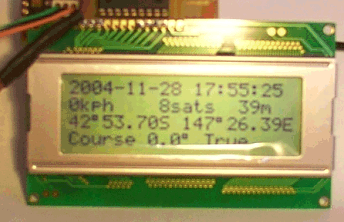
This is my gps display for the car- currently it uses a 16F628 running at 12MHz
Click here for the track layout, here for the component overlay,
here for the hex file for a 12 Mhz crystal and here for the hex file for a 10 Mhz crystal
The board is designed to solder directly to the connector on the rear of the display, but it is no problem to connect via a short cable if required. The contrast pot can be board-mounted or front panel, whatever suits, value is not critical, anywhere betwen 1 and 50k.
The board accepts standard NMEA data at 4800 baud, 8 bits, and no parity, so most gps's with a NMEA data output should drive it. The only problem would be if the data is inverted, in which case a simple single transistor inverter will cure the problem.
Handbook_of_Time_Code_Formats.pdf
Fundamentals of Time and Frequency.pdf
Introduction to time and frequency metrology.pdf
Residual PM Noise Evaluation of Radio Frequency Mixers.pdf
Oncore MAX232 bottom layer.pdf
Oncore MAX232 parts layout.pdf
Number of visitors to this page so far: